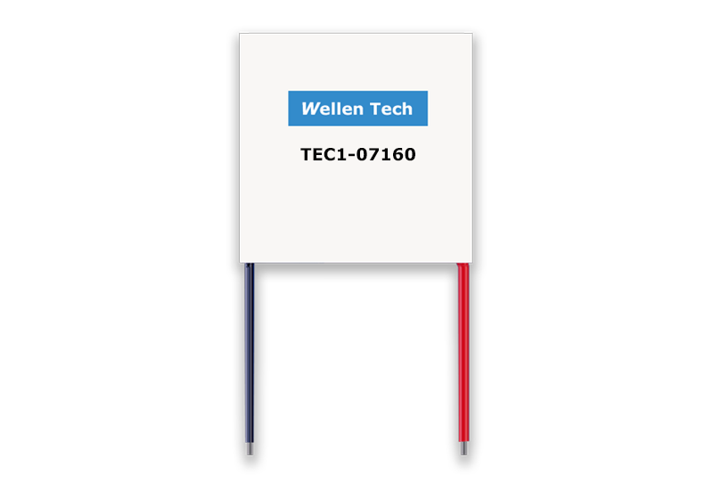
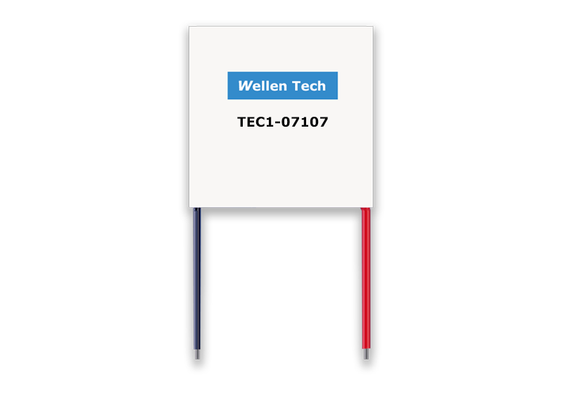
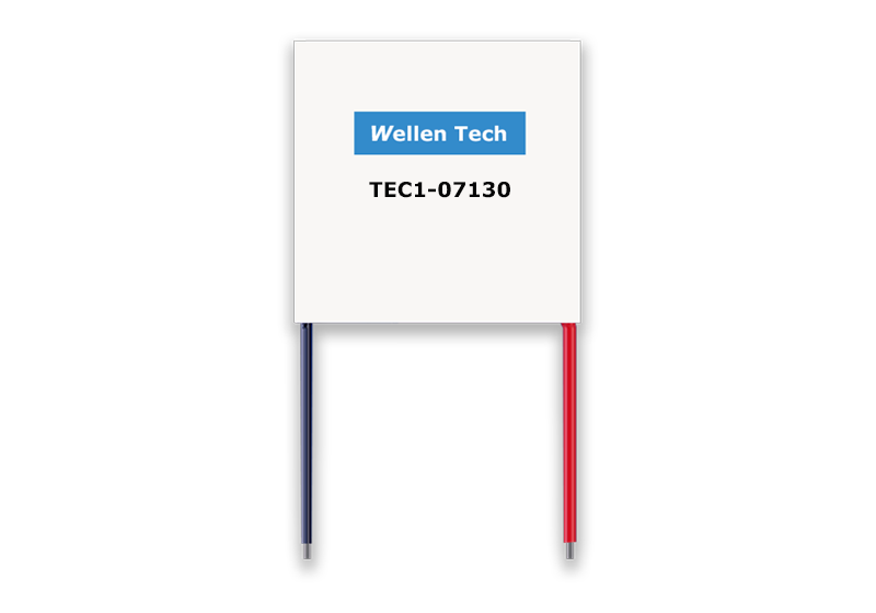
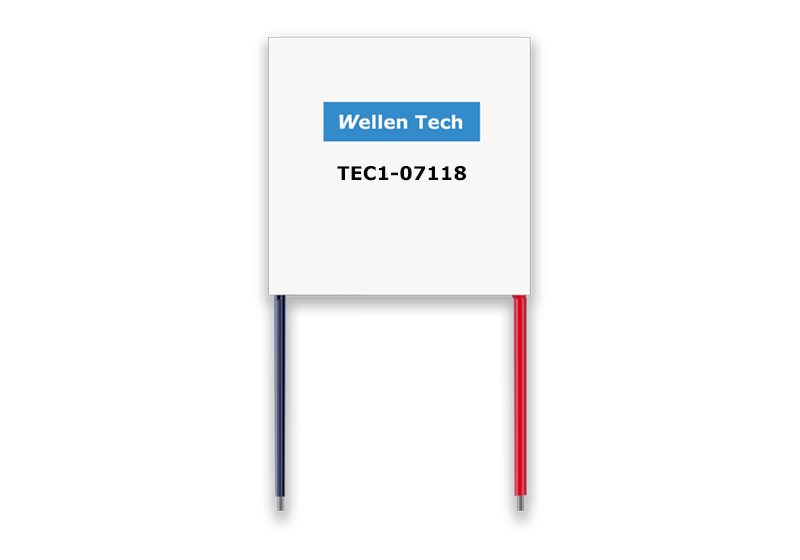
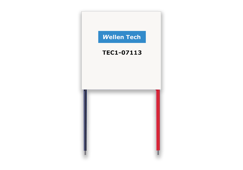
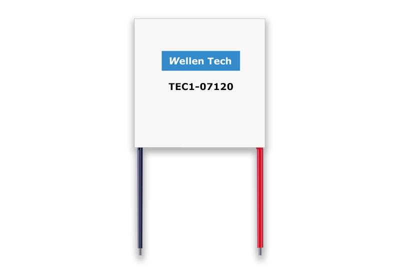
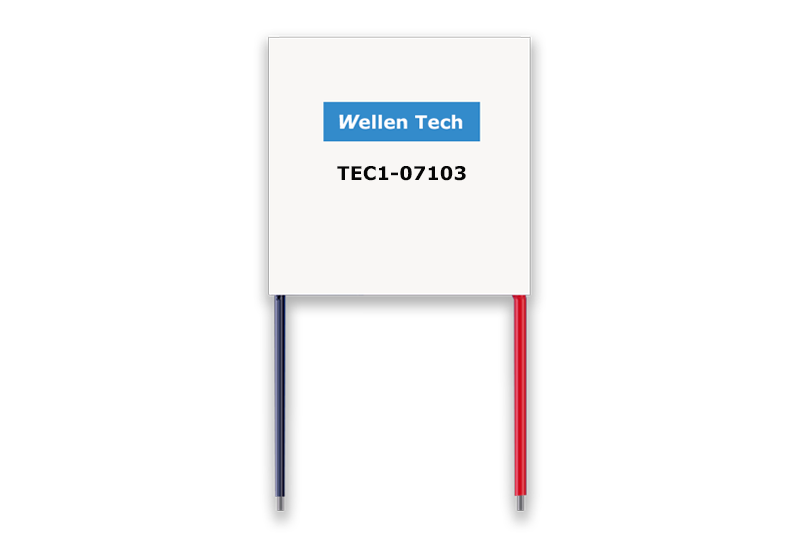
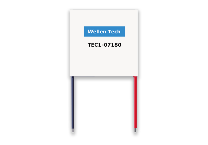
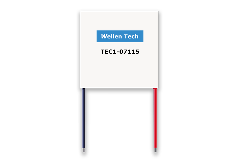
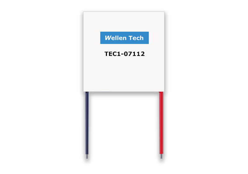
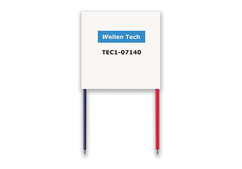
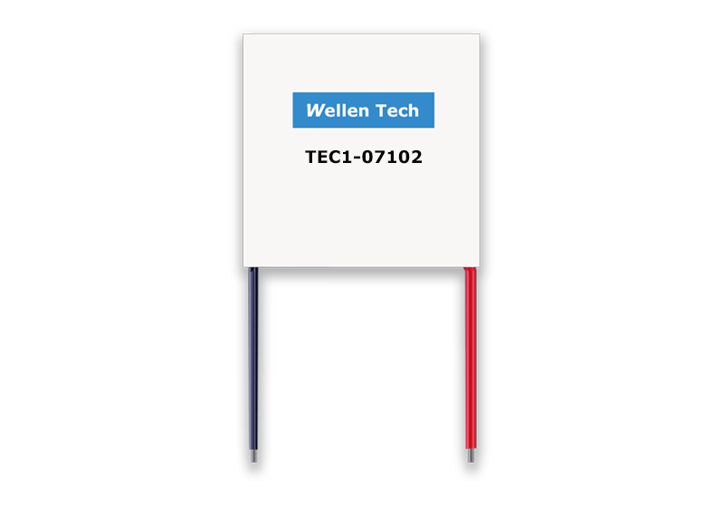
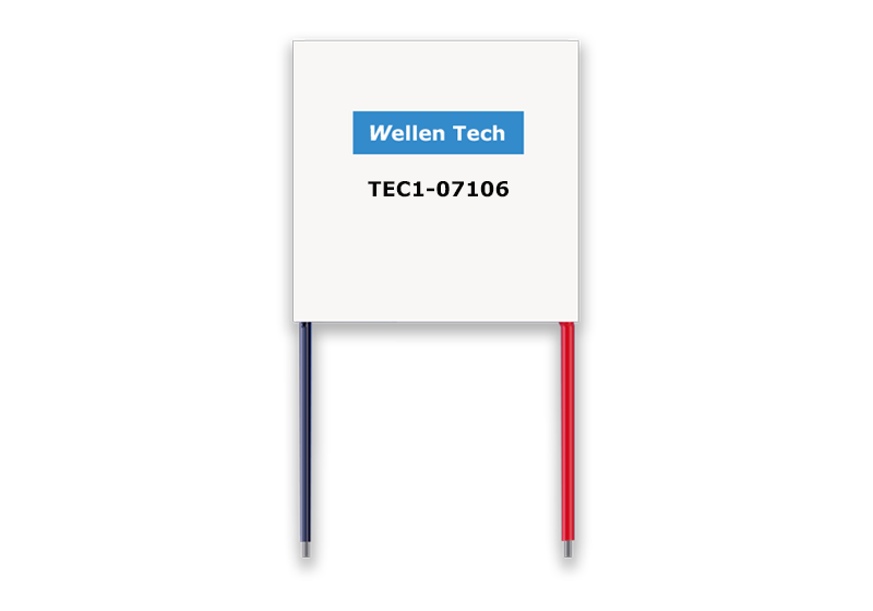
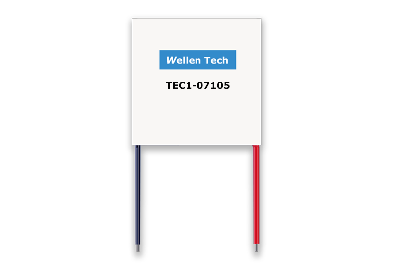
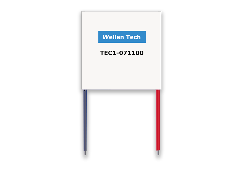
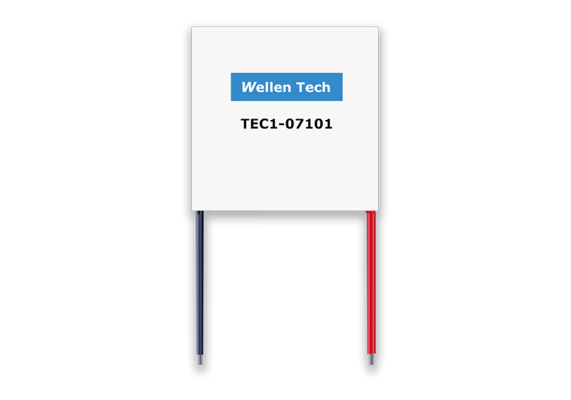
FEATURES:
● High efficiency, high performance.
● No Sound or Vibration.
● Compact structure, small in size, light in weight.
● Precise Temperature Control.
● Environmentally Friendly.
● RoHS compliant.
● Exceptionally reliable.
APPLICATIONS:
● Medical Instrumentation.
● Laser products.
● Lab science instrumentation.
● Clinical diagnostic systems.
● Photonics systems.
● Electronic enclosure cooling.
● Food & beverage cooling
● Chillers (Liquid Cooling).
● Temperature stabilizer.
PERFORMANCE SPECIFICATIONS
| Parameters | Remarks |
| Imax. | 60 A | Maximum current at ⊿Tmax. |
| Vmax. | 8.4 V | Maximum voltage at ⊿Tmax |
| Th=27℃ |
|
| Qmax. | 298.2 W | Maximum cooling capacity at Imax.,Vmax. and ⊿T=0℃. |
| ⊿Tmax. | 67 ℃ | Maximum temperature difference at Imax.,Vmax. and Q=0W |
| Solder melting point | 5.73℃ | Thermoelectric module's solder melting point |
| Maximum. compress. | 98.07N/cm2 | Recommended maximum compression (not destruction limit) |
OUTLINE DRAWING
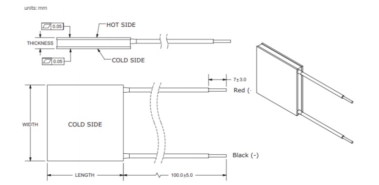
| Bottom L (mm) | Bottom W (mm) | Top L (mm) | Top W (mm) | Thickness |
| 55±0.3 | 55±0.3 | 55±0.3 | 55±0.3 | 4.3±0.1 |
| Item: | Options |
| Ceramic plate: | 96%Al2 O3 ,white (standard) |
| Ceramics Surface Options: | 1. Blank ceramics (standard)
2. Metallized (Au plating) |
| Sealing: | 1. NS: No sealing
2. SS: Silicone sealant (standard)
3. EPS: Epoxy sealant
4. Customer specify sealing |
| Soldering : | 1. 138℃ (standard)
2. 238 ℃
3. Others |
| Marking: | Print the Part No. on the cold side surface or hot side surface |
| Lead wire: | Heat-resistant:105°C
Wire: AWG#20 or equal、Tin-plating
1. Lead wire length 150 mm (standard)
2. Customer requirement |
| Dimension: | Except silicon rubber RTV |
ATTENTION
1. If you want to know which side of the TE module is the hot side and which is the cold side, you can connect the red wire to the positive polarity of the power supply, and the black wire to the negative polarity, then put through the current (without the heat sink to dissipate the energy), then use your hand to touch the bon the sides of the TE modules, you will feel that one side is hot and the other side is cold, so the hot side can be distinguished from the cold side. There is something to be mentioned, the time to flow cannot last more than 5 minutes, otherwise the TE may be damaged.
2. Generally, the red wire symbolizes the positive polarity, and the black wire stands for the negative polarity, so when you use it, just connect the red wire to the positive polarity of the power supply and the black wire to the negative polarity. If you want to change the hot side to the cold side, just reverse the polarity of the power supply. You should apply the DC power supply and the fluctuation coefficient should be less than 10%.
3. When cooling and heating get to be exchanged, you should wait until the hot side and the cold side get back to the room temperature, (more than 15 minutes), otherwise, the TE module may be damaged easily.
4. How to know the maximal voltage and the thermocouples' number of the TE module? The number of the thermocouples is the number of the crunodes between P type and N type. For example: the TE module TEC1-12706, 127 is the number of the thermocouples, 06 is the permissible current (unit: A); the maximal voltage≈ the number of thermocouples×0.12, for example: The maximal voltage of TEC1-12703 (V)= 127×0.12=15.2(V)。
5. In the main performance parameters of table, The value of △ Tmax, Vmax, Imax and Qcmax are the limited valuve abtained according to the standard of SJ2855-2858 and SJ/T10135-10137-91,They are just for the selection of reference . In the practical application , the voltage of 127 series can be controlled within the general 12-13V. With the average working temperature increaseing ,the current will decline.
6. In order to prolong the life of the TE modules, the TE modules should be sealed. There are two ways to sealing the TE modules: one way is to use the 704 silica gel, the other way is epoxy sealing. The aim of the sealing is to separate or isolate the TE modules from the outside air, thus the TE modules can be protected from dampness and moisture, and their life can be prolonged too.
7. Install the TE modules, first, you should clean the both sides of the TE modules, and daub the both sides with a layer of conducting-heat silicon resin; then the heatsinks, which will contact with the TE modules, should be smooth and cleaned, and daubed with a layer of conducting-heat silicon resin too; when install, the TE modules' cold sides and hot sides should have a good contact with the cold-plate and heat sink (you can also use screw to fix them, but should be careful). In order to get a better cooling effect, you can use heat insulation materials to fill the space between cold-plate and heat sink (the thickness is about 25-30mm).
8. Testing the resistance of the TE module is the main method to judge it is good or not, if you don't have the professional instrument, you can use bridge or ohmmeter to test the resistance. Note: the static state resistance tested by the multimeter is not exact, just for reference.
9. When carry and install the TE modules, the workman should be careful. Throwing the TE modules from high altitude is strictly prohibited, even the height is 10-20cm, the throwing can change the resistance, and the TE can be damaged.


